
Tutorial: Rendering 2D Shapes
Now that we've put Hello World on the screen, let's draw some more interesting shapes.
Step 1: Render colored rectangle
A shader is a type of program that runs on the GPU. Typically the process of rendering using shaders goes through multiple stages:
- Geometry Definition — defining the base geometry figure, which can be as simple as a rectangle or as complex as a teapot (which we'll look at in Tutorial: Rendering 3D Meshes).
- Vertex Shader — transforming the geometry's coordinates into screen coordinates.
- Rasterization — determining which pixels are inside the figure.
- Pixel Shader — computing the color of each pixel inside the rasterized figure.
- Instancing — repeat the above process for multiple instances of the same geometry, with some different instance-specific variables each time (like color or position).
See Learn OpenGL for an example how this works in OpenGL.
Now let's go through the process of creating our own shader using Zaplib. First, write a function that builds a geometry:
fn build_geom() -> Geometry {
    let vertex_attributes = vec![
        // top left vertex
        vec2(0., 0.),
        // top right vertex
        vec2(1., 0.),
        // bottom right vertex
        vec2(1., 1.),
        // bottom left vertex
        vec2(0., 1.),
    ];
    let indices = vec![
        // top-right triangle
        [0, 1, 2],
        // bottom-left triangle
        [2, 3, 0],
    ];
    Geometry::new(vertex_attributes, indices)
}
This function defines 2 adjacent triangles that form a rectangle.
Define a SHADER object:
static SHADER: Shader = Shader {
    build_geom: Some(build_geom),
    code_to_concatenate: &[
        Cx::STD_SHADER,
        code_fragment!(
            r#"
            geometry geom: vec2;
            instance color: vec4;

            fn vertex() -> vec4 {
                return vec4(geom.x, geom.y, 0., 1.);
            }

            fn pixel() -> vec4 {
                return color;
            }
            "#
        ),
    ],
    ..Shader::DEFAULT
code_to_concatenateis the custom code assigned to the shader. We addCx::STD_SHADERas a first argument which is a standard library of shaders within Zaplib.geometryis a qualifier that defines the data passed frombuild_geomoutput. Since ourvertex_attributesinbuild_geomconsist ofVec2objects, we define it as such here.instanceis a qualifier that defines an instance-specific variable — more about that later.coloris used to define which color to use for rectangle.fn vertex()defines the vertex shader. This gets called for each vertex returned frombuild_geom, withgeomgetting set to the corresponding point. It returnsvec4(x, y, z, w)where the values mean the following:x, y— coordinates on the screen (from -1 to 1).z— draw order (from 0 to 1). Draws with higherzwill be on top.w— normalization parameter. Not very important for now, so we'll set it currently to 1.0.
fn pixel()defines the pixel shader. Since we are not drawing any special shapes yet, we'll set every pixel to the same color. The pixel shader is called once for each pixel in the output image.
Define the struct to pass the color into the shader as an instance variable:
#[derive(Clone, Copy)]
#[repr(C)]
struct RectIns {
    color: Vec4,
}
Now we can combine all of this together and use the following draw function in our application:
    fn draw(&mut self, cx: &mut Cx) {
        self.window.begin_window(cx);
        self.pass.begin_pass(cx, Vec4::color("0"));
        self.view.begin_view(cx, LayoutSize::FILL);

        let color = vec4(1., 0., 0., 1.);
        cx.add_instances(&SHADER, &[RectIns { color }]);

        self.view.end_view(cx);
        self.pass.end_pass(cx);
        self.window.end_window(cx);
let colordefines the red color.cx.add_instancestakes a shader and passes theMyInsdata into it. Under the hood this creates a new "draw call".
You can run this full example with Cargo:
cargo run -p tutorial_2d_rendering_step1
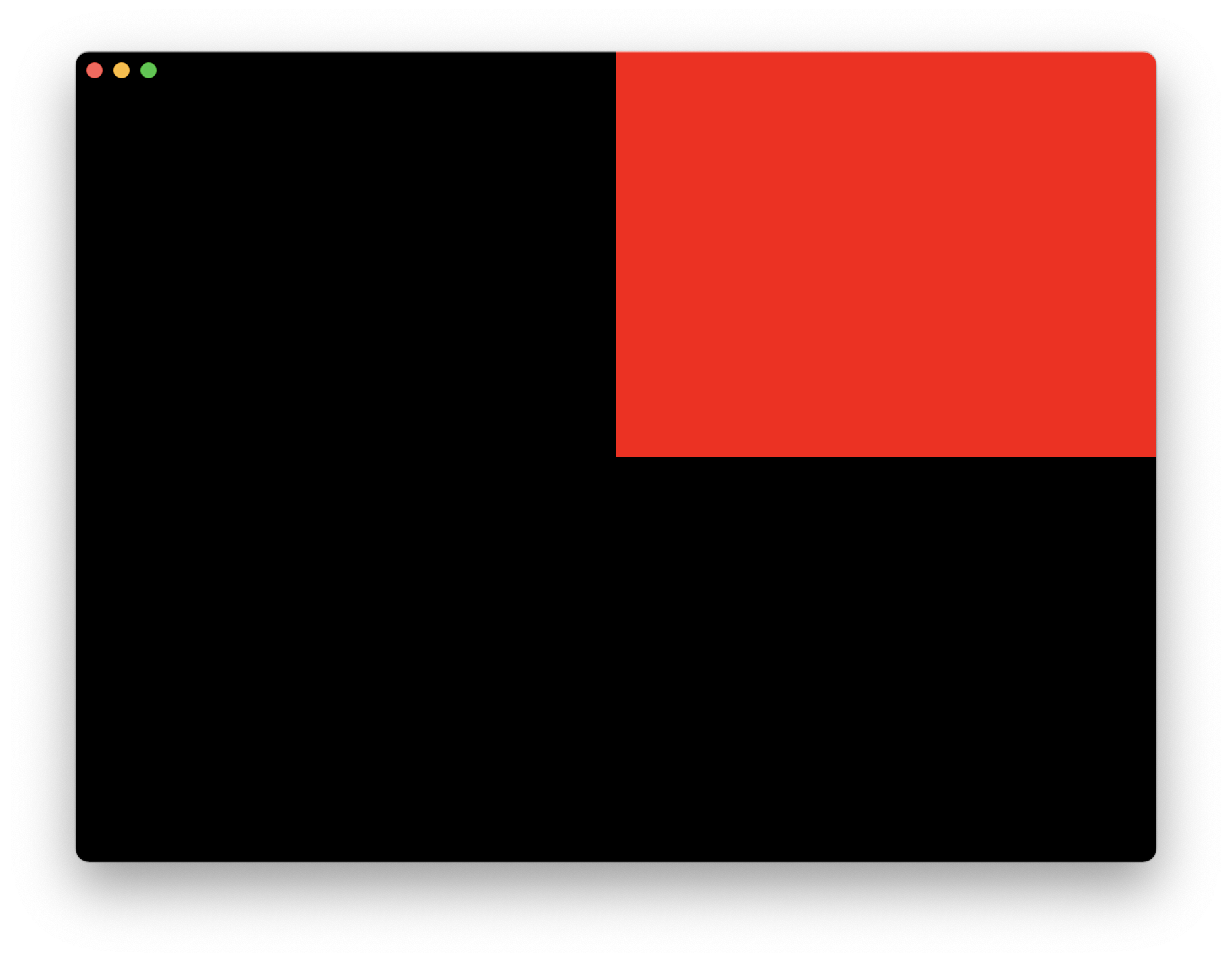
Note: the coordinates of vertices returned from vertex() shader are in [0; 1] range, while the window canvas uses [-1; 1]. That's why we see a red rectangle covering only a quarter of the window. In the next section we'll see how to draw with pixel coordinates.
Step 2: Render multiple bordered rectangles
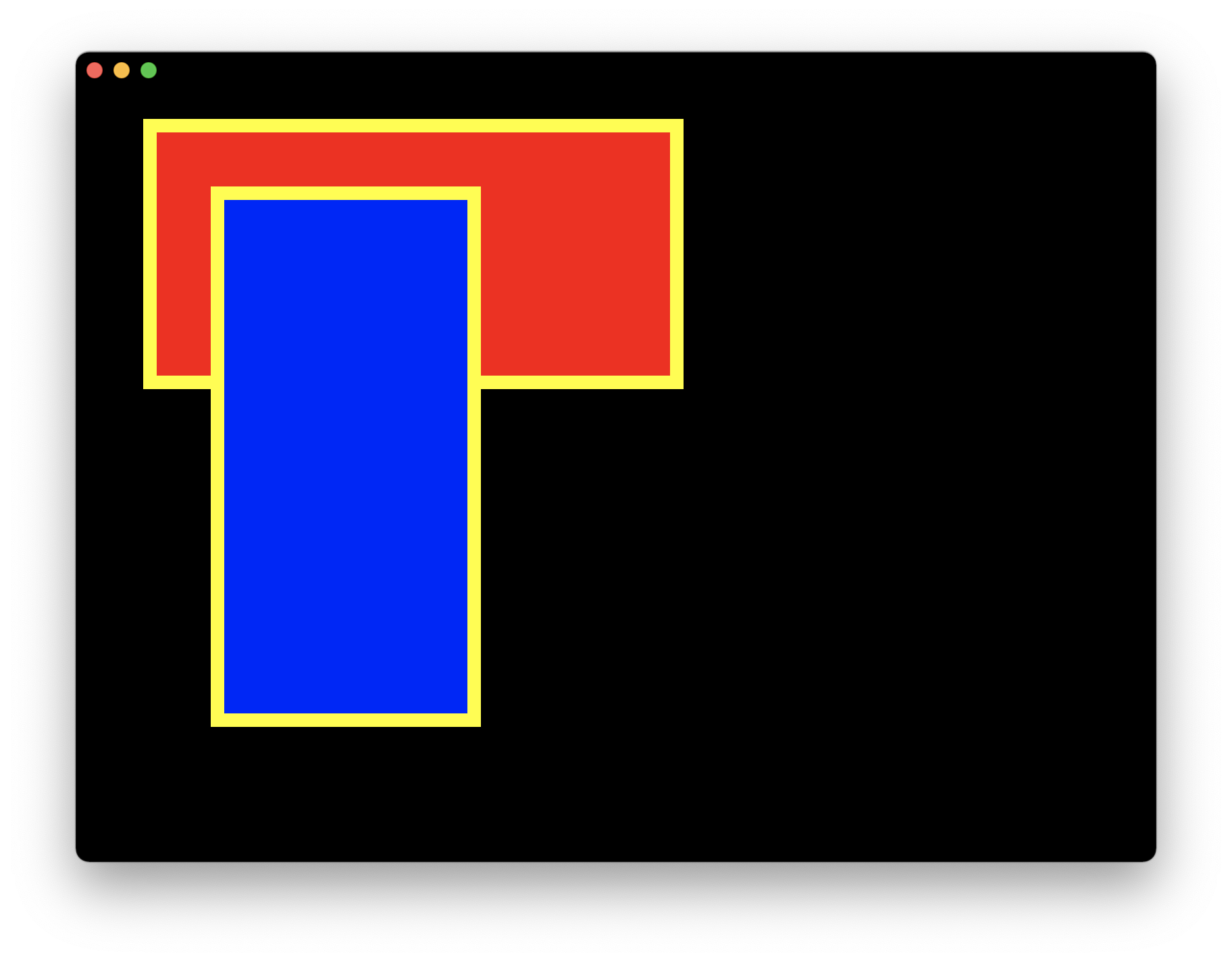
Now let's modify our example to draw 2 bordered rectangles of the given sizes on top of each other.
Modify RectIns to include the top-left position of rectangle and its size:
#[derive(Clone, Copy)]
#[repr(C)]
struct RectIns {
    color: Vec4,
    rect_pos: Vec2,
    rect_size: Vec2,
}
Update the shader code:
        code_fragment!(
            r#"
            geometry geom: vec2;
            instance color: vec4;
            instance rect_pos: vec2;
            instance rect_size: vec2;
            varying pos: vec2;

            fn vertex() -> vec4 {
                let point = geom * rect_size + rect_pos;
                pos = (point - rect_pos) / rect_size;
                return camera_projection * camera_view * vec4(point.x, point.y, 0., 1.);
            }

            fn pixel() -> vec4 {
                let border = 10.;
                let pt = pos * rect_size;
                if pt.x < border || pt.y < border || pt.x > rect_size.x - border || pt.y > rect_size.y - border {
                    return vec4(1., 1., 0., 1.0);
                }
                return color;
            }
instancevariablescolor,rect_pos,rect_sizedefine the data passed into the shader. They must be in the same order as the fields of theRectInsstruct.varying posdefines a local variable that gets passed fromvertex()shader to thepixel()shader.- Inside
vertex()we transform the geometry points to absolute coordinates of the rectangle to draw. In the end we applycamera_projectionandcamera_view, which are helper structs built into Zaplib that transform the absolute coordinates in pixels on the screen to[-1; 1]range. - Inside
pixel()we define a 10 pixel border and return yellow for the pixels within that border, andcolorfor other pixels in that rectangle.
Finally, update the draw function to pass the new RectIns struct with new colors and positions of rectangles to draw:
    fn draw(&mut self, cx: &mut Cx) {
       self.window.begin_window(cx);
       self.pass.begin_pass(cx, Vec4::color("0"));
       self.view.begin_view(cx, LayoutSize::FILL);

       let rect1 = RectIns { color: vec4(1., 0., 0., 1.), rect_pos: vec2(50., 50.), rect_size: vec2(400., 200.) };
       let rect2 = RectIns { color: vec4(0., 0., 1., 1.), rect_pos: vec2(100., 100.), rect_size: vec2(200., 400.) };

       cx.add_instances(&SHADER, &[rect1, rect2]);

       self.view.end_view(cx);
       self.pass.end_pass(cx);
       self.window.end_window(cx);
   }
You can run this full example with Cargo:
cargo run -p tutorial_2d_rendering_step2
Step 3: Using QuadIns
Drawing rectangles is very common in graphics, so Zaplib provides a convenient QuadIns struct. Let's use it in our latest example.
Update the SHADER definition:
static SHADER: Shader = Shader {
    build_geom: Some(QuadIns::build_geom),
    code_to_concatenate: &[
        Cx::STD_SHADER,
        QuadIns::SHADER,
        code_fragment!(
            r#"
            instance color: vec4;
            fn pixel() -> vec4 {
                let border = 10.;
                let pt = pos * rect_size;
                if pt.x < border || pt.y < border || pt.x > rect_size.x - border || pt.y > rect_size.y - border {
                    return vec4(1., 1., 0., 1.0);
                }
                return color;
            }
            "#
        ),
    ],
    ..Shader::DEFAULT
};
- Pass in the
QuadIns::build_geomfunction — it is identical to thebuild_geomfunction we defined above! - Prefix the shader with
QuadIns::SHADER. This defines avertex()shader, so we can remove that code. - We can remove
geom,rect_pos,rect_size, andpos, since those are also defined insideQuadIns::SHADER.
Update RectIns to use QuadIns instead of rect_pos and rect_size:
#[repr(C)]
struct RectIns {
    quad: QuadIns,
    color: Vec4,
}
We put quad on top to match the order in which shaders are concatenated above
Finally, change the draw function to pass new RectIns objects to the add_instances calls:
    fn draw(&mut self, cx: &mut Cx) {
        self.window.begin_window(cx);
        self.pass.begin_pass(cx, Vec4::color("0"));
        self.view.begin_view(cx, LayoutSize::FILL);

        let rect1 = RectIns {
            quad: QuadIns { rect_pos: vec2(50., 50.), rect_size: vec2(400., 200.), draw_depth: 0. },
            color: vec4(1., 0., 0., 1.),
        };
        let rect2 = RectIns {
            quad: QuadIns { rect_pos: vec2(100., 100.), rect_size: vec2(200., 400.), draw_depth: 0. },
            color: vec4(0., 0., 1., 1.),
        };

        cx.add_instances(&SHADER, &[rect1, rect2]);

        self.view.end_view(cx);
        self.pass.end_pass(cx);
        self.window.end_window(cx);
You can run this full example with Cargo:
cargo run -p tutorial_2d_rendering_step3
The output hasn't changed:
This is what the full code looks like:
use zaplib::*;

#[derive(Clone, Copy)]
#[repr(C)]
struct RectIns {
    quad: QuadIns,
    color: Vec4,
}

static SHADER: Shader = Shader {
    build_geom: Some(QuadIns::build_geom),
    code_to_concatenate: &[
        Cx::STD_SHADER,
        QuadIns::SHADER,
        code_fragment!(
            r#"
            instance color: vec4;

            fn pixel() -> vec4 {
                let border = 10.;
                let pt = pos * rect_size;
                if pt.x < border || pt.y < border || pt.x > rect_size.x - border || pt.y > rect_size.y - border {
                    return vec4(1., 1., 0., 1.0);
                }
                return color;
            }
            "#
        ),
    ],
    ..Shader::DEFAULT
};

#[derive(Default)]
struct App {
    window: Window,
    pass: Pass,
    view: View,
}

impl App {
    fn new(_cx: &mut Cx) -> Self {
        Self::default()
    }

    fn handle(&mut self, _cx: &mut Cx, _event: &mut Event) {}

    fn draw(&mut self, cx: &mut Cx) {
        self.window.begin_window(cx);
        self.pass.begin_pass(cx, Vec4::color("0"));
        self.view.begin_view(cx, LayoutSize::FILL);

        let rect1 = RectIns {
            quad: QuadIns { rect_pos: vec2(50., 50.), rect_size: vec2(400., 200.), draw_depth: 0. },
            color: vec4(1., 0., 0., 1.),
        };
        let rect2 = RectIns {
            quad: QuadIns { rect_pos: vec2(100., 100.), rect_size: vec2(200., 400.), draw_depth: 0. },
            color: vec4(0., 0., 1., 1.),
        };

        cx.add_instances(&SHADER, &[rect1, rect2]);

        self.view.end_view(cx);
        self.pass.end_pass(cx);
        self.window.end_window(cx);
    }
}

main_app!(App);